INTRODUCTION TO THE BRAYTON CYCLE IN GAS TURBINES
The
purpose of this white papers on the Brayton Thermodynamic Cycle is to
provide a fairly non-technical introduction to the most important thermodynamic
cycle used in the gas turbine technology used by AscenTrust, LLC. (The Company)
in the design and installation of the first phase of the Nuclear
Technology Pebble Bed Modular Reactor (NTPBMR) prototype project. The NTPBMR power plant will eventually
use a very unique type of turbine cycle: The closed-loop, Brayton cycle helium
turbine. In order to realize this new
technology, the Company will first build conventional, natural-gas fired
power plants connected to an existing natural gas pipeline. Phase two will be to build conventional
natural-gas fired power plants powered by LNG (Liquid Natural Gas). Phase three of the project will consist of
building a combustion chamber to heat the helium to be used in a closed-cycle
turbine which will be design in our research and development center. The 55MWe
closed-loop, helium powered gas turbine, will then form the basis for the Balance
of Plant for the 110MWe helium-cooled, graphite-moderated, pebble bed
nuclear power plant.
In order to introduce
the operations of a gas turbine we will have to review some basic concepts of
thermodynamics which were developed in the days of Joules and Carnot and are of
interest to anyone who has an interest in understanding the processes
involved in the production of
electricity through the use of thermal energy.
The source of thermal energy is the subject of other white papers in
this series. The final resting place of
the source of thermal energy for our project is of course the production of
energy through the use of nuclear power. Inherent in any discussion of thermodynamics
is the requirement for a basic understanding of the structure of matter, and certainly in the discussion of the
production of electrical energy through the fission of nuclear material are
some of the topics of modern physics: Quantum Mechanics and Special
Relativity. Very little will be said
in this paper concerning these two vast topics of Physics and Engineering. Even the statistical nature of thermodynamics
will not be mentioned.
A gas turbine, also called a combustion turbine, is a rotary
engine that extracts energy from a flow of combustion gas. The main components
of a gas turbine are: an upstream compressor coupled to a downstream turbine,
and a combustion chamber in-between. Energy is added to the gas stream in the
combustor, where fuel is mixed with air and ignited. In the high pressure
environment of the combustor, combustion of the fuel increases the temperature.
The products of the combustion are forced into the turbine section. There, the
high velocity and volume of the gas flow is directed through a nozzle over the
turbine's blades, spinning the turbine which powers the compressor and, for
some turbines, drives their mechanical output. The energy given up to the
turbine comes from the reduction in the temperature of the exhaust gas. Energy
is extracted in the form of shaft power, compressed air and thrust, in any
combination, and used to power aircraft, trains, ships, generators, and even
tanks.
SECTION ONE: CHARACTERISTICS OF THE BRAYTON CYCLE
1. INTRODUCTION: The Brayton
cycle was first proposed by George Brayton for use in the reciprocating
oil-burning engine that he developed around 1870. Today, it is used for gas
turbines only where both the compression and expansion processes take place in
rotating machinery. Both the compressors and the turbine are axial machines.
Gas turbines usually operate on an open cycle, as shown in
Fig. 1.1 below. Fresh air at ambient conditions is drawn into the compressor,
where its temperature and pressure are raised. The high pressure air proceeds
into the combustion chamber, where the fuel is burned at constant pressure. The
resulting high temperature gases then enter the turbine, where they expand to
the atmospheric pressure while producing power. The exhaust gases leaving the
turbine are thrown out (not recirculated), causing the cycle to be classified
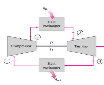
as an open cycle. The open gas-turbine cycle described above can be modeled as
a closed cycle, as shown in Fig. 1.2, by utilizing the air-standard
assumptions. Here the compression and expansion processes remain the same, but
the combustion process is replaced by a constant-pressure heat-addition process
from an external source, and the exhaust process is replaced by a constant
pressure heat-rejection process to the ambient air. The ideal cycle that the
working fluid undergoes in this closed loop is the Brayton cycle, which
is made up of four internally reversible processes:
- 1-2 Isentropic
compression (in a compressor)
- 2-3
Constant-pressure heat addition
- 3-4 Isentropic
expansion (in a turbine)
- 4-1
Constant-pressure heat rejection
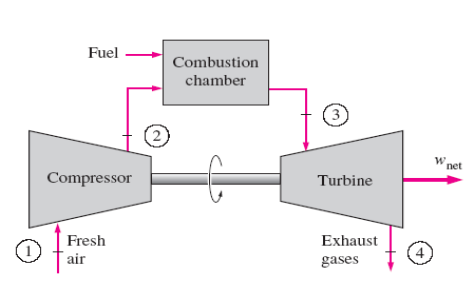
FIGURE 1.1. OPEN CYCLE GAS TURBINE
FIGURE
1.2. CLOSED-CYCLE GAS TURBINE
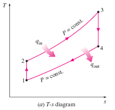
FIGURE 1.3(a). TEMPERATURE-ENTROPY DIAGRAM FOR BRAYTON CYCLE
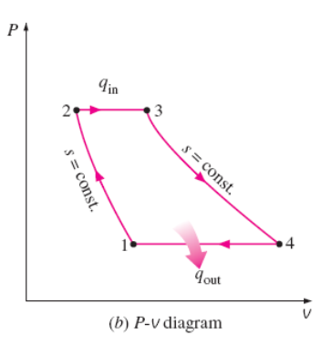
FIGURE 1.3 (b).
PRESSURE-VOLUME DIAGRAM FOR BRAYTON CYCLE
2.
Brayton Cycle Temperature: The highest
temperature in the cycle occurs at the end of the combustion process (state 3),
and it is limited by the maximum temperature that the turbine blades can
withstand. This also limits the pressure ratios that can be used in the cycle.
There should be a compromise between the pressure ratio (thus the thermal
efficiency) and the net work output. With less work output per cycle, a larger
mass flow rate (thus a larger system) is needed to maintain the same power
output, which may not be economical. In most common designs, the pressure ratio
of gas turbines ranges from about 11 to 16.
3.
Air in Gas Turbines: The air in gas
turbines performs two important functions: It supplies the necessary oxidant
for the combustion of the fuel, and it serves as a coolant to keep the
temperature of various components within safe limits. The second function is
accomplished by drawing in more air than is needed for the complete combustion
of the fuel. In gas turbines, an air–fuel mass ratio of 50 or above is not
uncommon. Therefore, in a cycle analysis, treating the combustion gases as air
does not cause any appreciable error. Also, the mass flow rate through the
turbine is greater than that through the compressor, the difference being equal
to the mass flow rate of the fuel. Thus, assuming a constant mass flow rate
throughout the cycle yields conservative results for open-loop gas-turbine
engines.
4.
Main Applications of Open-Cycle Gas
Turbines: The
two major application areas of gas-turbine engines are aircraft propulsion and
electric power generation. When it is used for aircraft propulsion, the
gas turbine produces just enough power to drive the compressor and a small
generator to power the auxiliary equipment. The high-velocity exhaust gases are
responsible for producing the necessary thrust to propel the aircraft.
5.
Combined-Cycle Gas Turbines: Gas
turbines are also used as stationary power plants to generate electricity as
stand-alone units or in conjunction with steam power plants on the
high-temperature side. In these plants, the exhaust gases of the gas turbine
serve as the heat source for the steam.
6.
Closed-Cycle, Helium, Gas Turbines: The
gas-turbine cycle can also be executed
as a closed cycle for use in nuclear power plants. This time the working fluid
is not limited to air, and a gas with more desirable characteristics (such as
helium) can be used.
7.
The majority of the Western world’s
naval fleets already use gas-turbine engines for propulsion and electric power
generation. The General Electric LM2500 gas turbines used to power ships have a
simple-cycle thermal efficiency of 37 percent. Many modern marine propulsion
systems use gas turbines together with diesel engines because of the high fuel
consumption of simple-cycle gas-turbine engines. In combined diesel and
gas-turbine systems, diesel is used to provide for efficient low-power and
cruise operation, and gas turbine is used when high speeds are needed.
8.
The General Electric WR-21 gas turbines
equipped with inter-cooling and regeneration have a thermal efficiency of 43
percent and produce 21.6 MW (29040 hp). The regeneration also reduces the
exhaust temperature from 600°C to 350°C. Air is compressed to 3 atm before it
enters the intercooler. Compared to steam-turbine and diesel propulsion
systems, the gas turbine offers greater power for a given size and weight, high
reliability, long life, and more convenient operation. The engine start-up time
has been reduced from 4 h required for a typical steam propulsion system to
less than 2 min for a gas turbine.
9. In
gas-turbine power plants, the ratio of the compressor work to the turbine work,
called the back work ratio, is very high. Usually more than one-half of
the turbine work output is used to drive the compressor. The situation is even
worse when the isentropic efficiencies of the compressor and the turbine are
low. This is quite in contrast to steam power plants, where the back work ratio
is only a few percent. This is not surprising, however, since a liquid is
compressed in steam power plants instead of a gas, and the steady-flow work is
proportional to the specific volume of the working fluid. A power plant with a
high back work ratio requires a larger turbine to provide the additional power
requirements of the compressor. Therefore, the turbines used in gas-turbine
power plants are larger than those used in steam power plants of the same net
power output.
SECTION TWO: DEVELOPMENTS IN BRAYTON CYCLE FOR
GAS TURBINES
The gas turbine has experienced
phenomenal progress and growth since its first successful development in the
1930s. The early gas turbines built in the 1940s and even 1950s had simple
cycle efficiencies of about 17 percent because of the low compressor and
turbine efficiencies and low turbine inlet temperatures due to metallurgical
limitations of those times. Therefore, gas turbines found only limited use
despite their versatility and their ability to burn a variety of fuels. The
efforts to improve the cycle efficiency concentrated in three areas:
1. Increasing the turbine
inlet (or firing) temperatures This has
been the primary approach taken to improve gas-turbine efficiency. The turbine
inlet temperatures have increased steadily from about 540°C in the 1940s to
1425°C and even higher today. These increases were made possible by the
development of new materials and the innovative cooling techniques for the
critical components such as coating the turbine blades with ceramic layers and
cooling the blades with the discharge air from the compressor. Maintaining high
turbine inlet temperatures with an air-cooling technique requires the
combustion temperature to be higher to compensate for the cooling effect of the
cooling air. However, higher combustion temperatures increase the amount of
nitrogen oxides (NOx), which are responsible for the formation of ozone
at ground level and smog. Using steam as the coolant allowed an increase in the
turbine inlet temperatures by 200°F without an increase in the combustion
temperature. Steam is also a much more effective heat transfer medium than air.
2. Increasing the
efficiencies of turbomachinery components: The
performance of early turbines suffered greatly from the inefficiencies of
turbines and compressors. However, the advent of computers and advanced
techniques for computer-aided design made it possible to design these
components aerodynamically with minimal losses. The increased efficiencies of
the turbines and compressors resulted in a significant increase in the cycle
efficiency.
3. Adding modifications to
the basic cycle: The simple-cycle
efficiencies of early gas turbines were practically doubled by incorporating
inter-cooling, regeneration (or recuperation), and reheating, discussed in the
next two sections. These improvements, of course, come at the expense of
increased initial and operation costs, and they cannot be justified unless the
decrease in fuel costs offsets the increase in other costs. The relatively low
fuel prices, the general desire in the industry to minimize installation costs,
and the tremendous increase in the simple-cycle efficiency to about 40 percent
left little desire for opting for these modifications. The first gas turbine
for an electric utility was installed in 1949 in Oklahoma as part of a
combined-cycle power plant. It was built by General Electric and produced 3.5
MW of power. Gas turbines installed until the mid-1970s suffered from low
efficiency and poor reliability. In the past, the base-load electric power
generation was dominated by large coal and nuclear power plants.
4.
Shift to Natural Gas-fired
gas turbines: There has been a historic shift toward natural gas–fired gas
turbines because of their higher efficiencies, lower capital costs, shorter
installation times, and better emission characteristics, and the abundance of
natural gas supplies, and more and more electric utilities are using gas
turbines for base-load power production as well as for peaking. The construction
costs for gas-turbine power plants are roughly half that of comparable
conventional fossil-fuel steam power plants, which were the primary base-load
power plants until the early 1980s. More than half of all power plants to be
installed in the foreseeable future are forecast to be gas turbine or combined
gas–steam turbine types.
5. Example of increase in efficiency and power of gas turbines: A gas
turbine manufactured by General Electric in the early 1990s had a pressure
ratio of 13.5 and generated 135.7 MW of net power at a thermal efficiency of 33
percent in simple-cycle operation. A more recent gas turbine manufactured by
General Electric uses a turbine inlet temperature of 1425°C and produces up to
282 MW while achieving a thermal efficiency of 39.5 percent in the simple-cycle
mode. A 1.3-ton small-scale gas turbine labeled OP-16, built by the Dutch firm
Opra Optimal Radial Turbine, can run on gas or liquid fuel and can replace a
16-ton diesel engine. It has a pressure ratio of 6.5 and produces up to 2 MW of
power. Its efficiency is 26 percent in the simple-cycle operation, which rises
to 37 percent when equipped with a regenerator.
SECTION
THREE: THE BRAYTON CYCLE WITH REGENERATION
In gas-turbine engines, the
temperature of the exhaust gas leaving the turbine is often considerably higher
than the temperature of the air leaving the compressor. Therefore, the high
pressure air leaving the compressor can be heated by transferring heat to it
from the hot exhaust gases in a counter-flow heat exchanger, which is also
known as a regenerator or a recuperator. A sketch
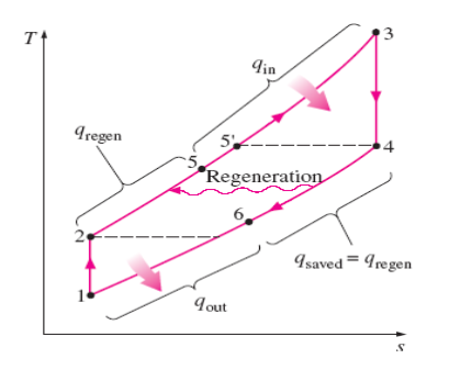
of the gas-turbine engine utilizing a regenerator and the T-s diagram
of the new cycle are shown in in the figures below:
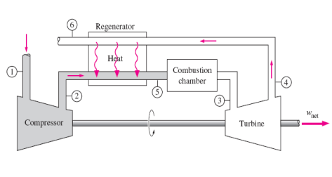
The thermal efficiency of
the Brayton cycle increases as a result of regeneration since the portion of
energy of the exhaust gases that is normally rejected to the surroundings is
now used to preheat the air entering the combustion chamber. This, in turn,
decreases the heat input (thus fuel) requirements for the same net work output.
Note, however, that the use of a regenerator is recommended only when the
turbine exhaust temperature is higher than the compressor exit temperature.
Otherwise, heat will flow in the reverse direction (to the exhaust
gases), decreasing the efficiency. This situation is encountered in gas-turbine
engines operating at very high pressure ratios.
The highest temperature occurring within the
regenerator is T4, the temperature of the exhaust gases leaving the
turbine and entering the regenerator. Under no conditions can the air be
preheated in the regenerator to a temperature above this value. Air normally
leaves the regenerator at a lower temperature, T5. In the limiting
(ideal) case, the air exits the regenerator at the inlet temperature of the
exhaust
SECTION
FOUR: THE BRAYTON CYCLE WITH INTERCOOLING, REHEATING, AND REGENERATION
4.1.
Multistage Compression with
Intercooling: The net work of a gas-turbine cycle
is the difference between the turbine work output and the compressor work
input, and it can be increased by either decreasing the compressor work or
increasing the turbine work, or both. As mentioned before that the work
required to compress a gas between two specified pressures can be decreased by
carrying out the compression process in stages and cooling the gas in between
—that is, using multistage compression with intercooling. As the number of stages is increased, the
compression process becomes nearly isothermal at the compressor inlet temperature,
and the compression work decreases.
4.2.
Multistage Expansion with
re-heating: Likewise, the work output of a
turbine operating between two pressure levels can be increased by expanding the
gas in stages and reheating it in between—that is, utilizing multistage
expansion with reheating. This is accomplished without raising the maximum
temperature in the cycle. As the number of stages is increased, the expansion
process becomes nearly isothermal. The foregoing argument is based on a simple
principle:
4.3.
Intercooling and
Re-heat: The steady-flow compression or expansion work is proportional to
the specific volume of the fluid. Therefore, the specific volume of the working
fluid should be as low as possible during a compression process and as high as
possible during an expansion process. This is
precisely what intercooling and reheating accomplish. Combustion in gas
turbines typically occurs at four times the amount of air needed for complete
combustion to avoid excessive temperatures. Therefore, the exhaust gases are
rich in oxygen, and reheating can be accomplished by simply spraying additional
fuel into the exhaust gases between two expansion states.
The working fluid leaves the
compressor at a lower temperature, and the turbine at a higher temperature,
when intercooling and reheating are utilized. This makes regeneration more
attractive since a greater potential for regeneration exists. Also, the gases
leaving the compressor can be heated to a higher temperature before they enter
the combustion chamber because of the higher temperature of the turbine
exhaust.
A schematic of the physical arrangement and the T-s diagram
of an ideal two-stage gas-turbine cycle with intercooling, reheating, and
regeneration are shown in the figures below:
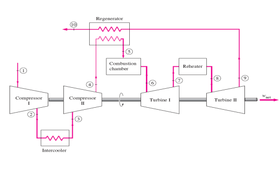
FIGURE 4(a). DIAGRAM OF TWO STAGE TURBINE WITH INTERCOOLING, REHEATING AND REGENERATION
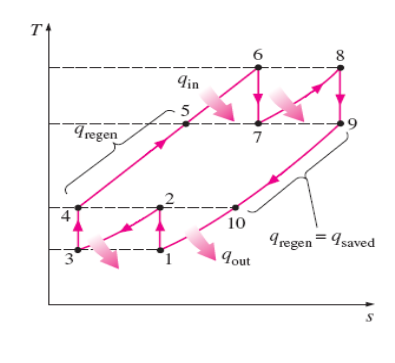
FIGURE 4(b). TEMPERATURE/ENTROPY DIAGRAM, TWO STAGE TURBINE WITH INTERCOOLING, REHEATING AND REGENERATION
The gas enters the first stage of the compressor at state 1, is
compressed isentropically to an intermediate pressure P2, is cooled at
constant pressure to state 3 (T3 = T1), and is compressed in the
second stage isentropically to the final pressure P4. At state 4 the gas
enters the regenerator, where it is heated to T5 at constant pressure.
In an ideal regenerator, the gas leaves the regenerator at the temperature of
the turbine exhaust, that is, T5 = T9. The primary heat addition
(or combustion) process takes place between states 5 and 6. The gas enters the
first stage of the turbine at state 6 and expands isentropically to state 7,
where it enters the reheater. It is reheated at constant pressure to state 8 (T8
= T6), where it enters the second stage of the turbine. The gas exits
the turbine at state 9 and enters the regenerator, where it is cooled to state
10 at constant pressure. The cycle is completed by cooling the gas to the
initial state (or purging the exhaust gases).
SECTION
FIVE: IDEAL JET-PROPULSION CYCLES
5.1.
Introduction: Gas-turbine
engines are widely used to power aircraft because they are light and compact
and have a high power-to-weight ratio. Aircraft gas turbines operate on an open
cycle called a jet propulsion cycle. The ideal jet propulsion cycle
differs from the simple ideal Brayton cycle in that the gases are not expanded
to the ambient pressure in the turbine. Instead, they are expanded to a
pressure such that the power produced by the turbine is just sufficient to
drive the compressor and the auxiliary equipment, such as a small generator and
hydraulic pumps. That is, the net work output of a jet propulsion cycle is
zero. The gases that exit the turbine at a relatively high pressure are
subsequently accelerated in a nozzle to provide the thrust to propel the
aircraft (See figure below).
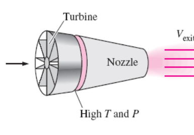
Also, aircraft gas turbines operate at higher pressure ratios
(typically between 10 and 25), and the fluid passes through a diffuser first,
where it is decelerated and its pressure is increased before it enters the
compressor. Aircraft are propelled by accelerating a fluid in the opposite
direction to motion. This is accomplished by either slightly accelerating a
large mass of fluid ( propeller-driven engine) or greatly accelerating a
small mass of fluid ( jet or turbojet engine) or both (turboprop
engine). A schematic of a turbojet
engine and the T-s diagram of the ideal turbojet cycle are shown
in the figures below:
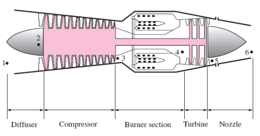
FIGURE 5 (a): SCHEMATIC OF A TURBOJET ENGINE
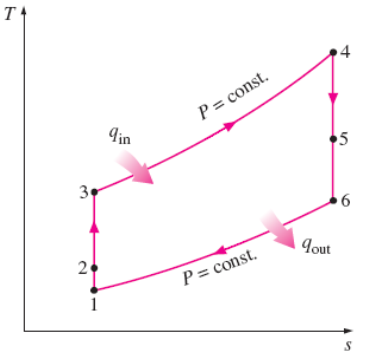
FIGURE 5(b): TEMPERATURE-ENTROPY DIAGRAM FOR THE TURBOJET CYCLE
The pressure of air rises
slightly as it is decelerated in the diffuser. Air is compressed by the
compressor. It is mixed with fuel in the combustion chamber, where the mixture
is burned at constant pressure. The high-pressure and high-temperature
combustion gases partially expand in the turbine,
producing enough power to drive the compressor and other equipment. Finally,
the gases expand in a nozzle to the ambient pressure and leave the engine at a
high velocity. In the ideal case, the turbine work is assumed to equal the
compressor work. Also, the processes in the diffuser, the compressor, the
turbine, and the nozzle are assumed to be isentropic. In the analysis of actual
cycles, however, the irreversibilities associated with these devices should be
considered. The effect of the irreversibilities is to reduce the thrust that
can be obtained from a turbojet engine. The thrust developed in a
turbojet engine is the unbalanced force that is caused by the difference in the
momentum of the low-velocity air entering the engine and the high-velocity
exhaust gases leaving the engine, and it is determined from Newton’s second
law.
SECTION SIX: TURBOFAN ENGINES
The first
airplanes built were all propeller-driven, with propellers
powered by engines essentially identical to automobile engines. The major
breakthrough in commercial aviation occurred with the introduction of the
turbojet engine in 1952. Both propeller-driven engines and jet-propulsion
driven engines have their own strengths and limitations, and several attempts
have been made to combine the desirable characteristics of both in one engine.
The most widely used engine in aircraft propulsion is the turbofan (or fanjet)
engine wherein a large fan driven by the turbine forces a considerable amount
of air through a duct (cowl) surrounding the engine, as shown in the figures
below.
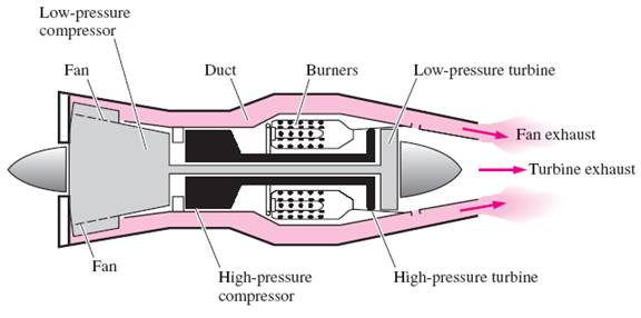
FIGURE
6(a): SCHEMATIC OF A TURBOFAN AIRCRAFT ENGINE
The fan exhaust
leaves the duct at a higher velocity, enhancing the total thrust of the engine
significantly. A turbofan engine is based on the principle that for the same
power, a large volume of slower moving air produces more thrust than a small
volume of fast-moving air.
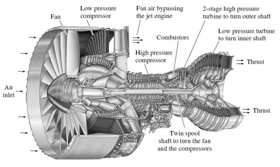
FIGURE 6(b): SECTION OF A MODERN
TURBOFAN JET ENGINE
The jet engine shown above is used to
power the Boeing 777 aircraft. This is a Pratt & Whitney PW4084 turbofan
capable of producing 84,000 pounds of thrust. It is 4.87 m (192 in.) long, has
a 2.84 m (112 in.) diameter fan, and it weighs 6800 kg (15,000 lbm).
The turbofan engine on an airplane can
be distinguished from the less efficient turbojet engine by its fat cowling
covering the large fan. All the thrust of a turbojet engine is due to the
exhaust gases leaving the engine at about twice the speed of sound. In a
turbofan engine, the high-speed exhaust gases are mixed with the lower-speed
air, which results in a considerable reduction in noise.
New cooling techniques have resulted in
considerable increases in efficiencies by allowing gas temperatures at the
burner exit to reach over 1500°C, which is more than 100°C above the melting
point of the turbine blade materials. Turbofan engines deserve most of the
credit for the success of jumbo jets that weigh almost 400,000 kg and are
capable of carrying over 400 passengers for up to a distance of 10,000 km at
speeds over 950 km/h with less fuel per passenger mile.
The ratio of the mass flow rate of air
bypassing the combustion chamber to that of air flowing through it is called
the bypass ratio. The first commercial high-bypass-ratio engines had a
bypass ratio of 5. Increasing the bypass ratio of a turbofan engine increases
thrust. Thus, it makes sense to remove the cowl from the fan. The result is a propjet
engine.
Turbofan and propjet engines differ
primarily in their bypass ratios: 5 or 6 for turbofans and as high as 100 for
propjets. As a general rule, propellers are more efficient than jet engines,
but they are limited to low-speed and low-altitude operation since their
efficiency decreases at high speeds and altitudes.