Nuclear Technologies, Inc.
Preamble
Before we begin our discussion on the various nuclear technologies which have been and will be used by the Nuclear Industry we need to add a few paragraphs of context to the discussion, pro and con, for the use of nuclear energy.
We must first acknowledge the simple fact that we are here, and there are a lot of us - some 8 billion in the year 2022 and our population will most likely max out at approximately 10 billion in a few generations.
On the premise that life is worth living (and most of us think that way, otherwise our population wouldn't be growing), it follows that we should make the best of the situation. Quality of life is, thus, a worthy and meaningful pursuit. To achieve and maintain a reasonable quality of life requires energy. Access to energy is an enabling force, empowering society and individuals. In short, it is fundamental to our existence. Energy is not a panacea for the strife of life, to be sure; but without it, there would be no life at all.
If we look back on early societies we will appreciate the central role that access to energy has played in the development of these early human societies. Food and water are essential commodities for the human race. To supply these in adequate quantities to society has always been a challenge.
Ancient civilizations have met this challenge with remarkable feats of engineering such as the Roman aqueducts such as the Pont du Gard also demonstrate significant ingenuity to provide a single commodity. Most of these were built using human power only,which limited the rate of implementation and hence development.
This changed with the industrial revolution when first water power and then steam power became a source of energy to assist in the supply of food and water as well as clothing and transport. This supply of energy enabled society to implement new ideas and advance technology at a greater rate and to sustain an increase in population. Thus the human race became dependent upon another essential commodity, namely energy.
Some History
The nuclear industry in the United States, and Canada, grew out of the Manhattan Project, which was the large science and engineering effort during WWII that led to the development and use of the atomic bomb. Even today, the heritage continues to cast a shadow over the nuclear industry. The goal of the Manhattan Project was the production of very highly enriched uranium and very pure plutonium-239 contaminated with a minimum of other plutonium isotopes. These were the materials used in the production of atomic weapons. Today, excess quantities of these materials are being diluted so that they can be used in nuclear-powered electric generating plants.
Many see the commercial nuclear power station as a hazard to human life and the environment. Part of this is related to the atomic-weapon heritage of the nuclear reactor, but the ongoing anxiety is related to the reactor accidents. In the wake of the Three Mile Island, Chernobyl, and Fukushima nuclear events, the future of nuclear energy looked bleak as many nations are declaring themselves nuclear free.
The commercial nuclear industry began in the 1950s. In 1953, U.S. President Dwight D. Eisenhower addressed the United Nations and gave his famous “Atoms for Peace” speech where he pledged the United States “to find the way by which the miraculous inventiveness of man shall not be dedicated to his death, but consecrated to his life.” President Eisenhower signed the 1954 Atomic Energy Act, which fostered the cooperative development of nuclear energy by the Atomic Energy Commission (AEC) and private industry. This marked the beginning of the nuclear power program in the U.S.
Earlier on December 20, 1951, 45 kw of electricity was generated at the Experimental Breeder Reactor-I (EBR-I) in Arco, Idaho. The nuclear reactor in a nuclear power plant is a source of Energy (heat) used to produce steam that is used to turn the turbine of an electric generator. In that way it is no different from burning coal or natural gas in a boiler. The difference is that the source of energy does not come from burning a fossil fuel, but from splitting an atom. The atom is a much more concentrated energy source such that a single gram of uranium when split or fissioned will yield 1 megawatt day or 24,000 kilowatt hours of energy. A gram of coal will yield less than 0.01 kilowatt hours.
Nuclear power plant construction in the U.S. began in the 1950s. The Shippingport power station in Shippingport, Pennsylvania, was the first to begin operation in the U.S. It was followed by a series of demonstration plants of various designs most with electric generating capacity less then 100 Mw. During the late 1960s, there was a frenzy to build larger nuclear powered generating stations. By the late 1970s, many of these were in operation or under construction and many more had been ordered. When the accident at Three Mile Island occurred, activity in the U.S. essentially ceased and most orders were canceled as well as some reactors that were already under construction.
However, as concerns over rising energy cost and carbon dioxide production rises, nuclear energy is poised for a comeback. The US Department of Energy has adopted a positive views about nuclear energy and is providing funding for prototyping of small modular nuclear reactors. The International Atomic Energy Agency defines small scale nuclear reactors as those with an electricity output of less than 300 MWe. In comparison, traditional nuclear reactors have electrical output in the range from 500MWe to 1500MWe.
The nuclear industry today is truly international in scope. Major design and manufacturing companies work all over the world. The industry in the U.S. has survived the 30 years since the Three Mile Island accident, and is resurging to meet the coming requirements for the generation of electric energy. The companies may have new ownership and new names, but some of the people who began their careers in the 1970s are still hard at work and are involved in training the coming generations of workers.
It is important to recognize that when the commercial nuclear industry began, we did not have high-speed digital computers or electronic hand calculators. The engineers worked with vast tables of data and their slide-rules; draftsmen worked at a drawing board with a pencil and ruler. The data were compiled in handbooks and manually researched. Today, that information is available on the Internet and in the sophisticated computer programs that are used in the design and engineering process.
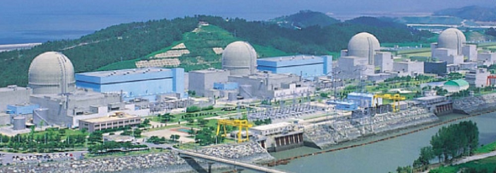
The first section of the document is devoted to nuclear power reactors. Sixteen percent of the electrical energy generated in the U.S. is generated in nuclear power plants. These plants are Pressurized Water Reactors (PWR) and Boiling Water Reactors (BWR). In Canada, nuclear energy is generated by the Canadian Deuterium Uranium Reactor (CANDU).
The Generation II PWRs were manufactured by Westinghouse, Combustion Engineering and Babcock and Wilcox, whereas the BWRs were manufactured by General Electric. These reactor systems are described in Section One of this document. The descriptions include the various reactor systems and components and general discussion of how they function. The preliminary discussion will not include the newer systems that are currently being proposed which have significant safety upgrades.
Section three of this document will be brief description of the CANDU reactor. The CANDU reactor is the reactor of choice in Canada. This reactor is unique in that it uses heavy water (sometimes called deuterium oxide) as its neutron moderator. Because it uses heavy water as a moderator, the reactor can use natural uranium as a fuel; therefore, the front-end of the fuel cycle does not include the uranium enrichment process required for reactors with a light water neutron moderator. The HTGR or gas cooled reactor was used primarily in the UK. Even though the basic designs of this power generating system have been available since the 1960s, the reactor concept never penetrated the commercial market to a great extent. Looking forward, this concept has many potential applications because the high temperatures can lead to increased effi- ciency in the basic power generating cycles.
The second section of the book is devoted to the nuclear fuel cycle and also facilities and processes related to the lifecycle of nuclear systems. The fuel cycle begins with the extrac- tion or mining of uranium ores and follows the material through the various processing steps before it enters the reactor and after it is removed from the reactor core. The material includes nuclear fuel reprocessing, even though it is not currently practised in the U.S., and also describes the decommissioning process which comes at the end of life for nuclear facilities. A special section is added at the end of the section to describe the CANDU fuel cycle. This is done because it is unique to that reactor concept.
AscenTrust, LLC., a Texas corporation, wholly owned by it's Founder and Senior Engineer, was Incorporated in 2009 to act as a joint venture with an Australian Investment Group, willing and able to finance the licensing and construction of the NTPBMR (Nuclear Technology Pebble Bed Modular Reactor).
Section Two: History
The Senior Engineer of AscenTrust has been involved with the study of lasers, plasmas, solid state physics, Neutron Physics and the Nuclear Industry since his days as a Graduate Student (1969-1973).
Land and Sea Enterprises, Inc. is a Texas Corporation formed in 1997, wholly owned by its Principal Engineer, Mr. Joseph Fournier. This corporation is the construction arm of the projects managed by the Senior Engineer of AscenTrust, LLC., .
In the January 2003 issue of Scientific American the following article appeared (Next Generation Nuclear Power). Reading this article, the Senior Engineer of Land and Sea Enterprises, Inc. was prompted to re-create the SMR (Small Modular Reactor) Design which he had studied and been involved with during his time as a Graduate Student (1969-1973). The focus of this article was the new gas-cooled reactors now known as the Pebble Bed Modular Reactor. The next generation nuclear technologies were introduced as: New, safer and more economical nuclear reactors that could not only satisfy many of our future energy needs but could combat global warming as well.
Over the next five years Mr. Fournier re-created the Design and Documents for his version of the pebble bed modular reactor. The result of this work was the creation of Nuclear Technologies, Inc. and the design documents which include the following Intro to NTPBMR.
During the 2006-2007 time frame the Senior Engineer of Land and Sea was negotiating with the North American arm of UBS (Formally Paine Webber) and Morgan Stanley, to finance the Design and licensing of the NTPBMR technology.
2.1: The Funding Entities
UBS Group AG is a multinational investment bank and financial services company founded and based in Switzerland. Co-headquartered in the cities of Zürich and Basel, it maintains a presence in all major financial centres as the largest Swiss banking institution and the largest private bank in the world. UBS client services are known for their strict bank–client confidentiality and culture of banking secrecy. Because of the bank's large positions in the Americas, EMEA, and Asia Pacific markets, the Financial Stability Board considers it a global systemically important bank. On 3 November 2000, UBS merged with Paine Webber, an American stock brokerage and asset management firm led by chairman and CEO Donald Marron. At the time of its merger with UBS, Paine Webber had emerged as the fourth largest private client firm in the United States with 385 offices employing 8,554 brokers. The acquisition pushed UBS to the top wealth and asset management firm in the world. Initially, the business was given the divisional name UBS Paine Webber but in 2003 the 123-year-old name Paine Webber disappeared when it was renamed UBS Wealth Management USA.
Morgan Stanley is an American multinational investment bank and financial services company headquartered at 1585 Broadway in Midtown Manhattan, New York City. With offices in 41 countries and more than 75,000 employees, the firm's clients include corporations, governments, institutions, and individuals. Morgan Stanley ranked No. 61 in the 2021 Fortune 500 list of the largest United States corporations by total revenue.
2.2: The Sub-prime Mortgage Problem
UBS: At the beginning of 2007, UBS became the first Wall Street firm to announce a heavy loss in the subprime mortgage sector as the subprime mortgage crisis began to develop. In May 2007, UBS announced the closure of its Dillon Read Capital Management (DRCM) division. Although in 2006, DCRM had generated a profit for the bank of US$720 million, after UBS took over DRCM's positions in May 2007, losses grew from the US$124 million recorded by DRCM, ultimately to "16% of the US$19 billion in losses UBS recorded." The UBS investment bank continued to expand subprime risk in the second quarter of 2007 while most market participants were reducing risk, resulting in not only expanding DRCM losses but creating the 84% of the other losses experienced by the bank.
Morgan Stanley In 2007, In order to cope with the write-downs during the subprime mortgage crisis, Morgan Stanley announced that it would receive a US$5 billion capital infusion from the China Investment Corporation in exchange for securities that would be convertible to 9.9% of its shares in 2010. The bank's Process Driven Trading unit was amongst several on Wall Street caught in a short squeeze, reportedly losing nearly $300 million in one day. The bubble's subsequent collapse was considered to be a central feature of the financial crisis of 2007–2010.
2.3: The Joint Venture
AscenTrust, LLC. was Incorporated in 2009 to act as a joint venture with an Australian Investment Group, willing and able to finance the licensing and construction of the NTPBMR (Nuclear Technology Pebble Bed Modular Reactor).
2.4: Fukushima Nuclear Accident
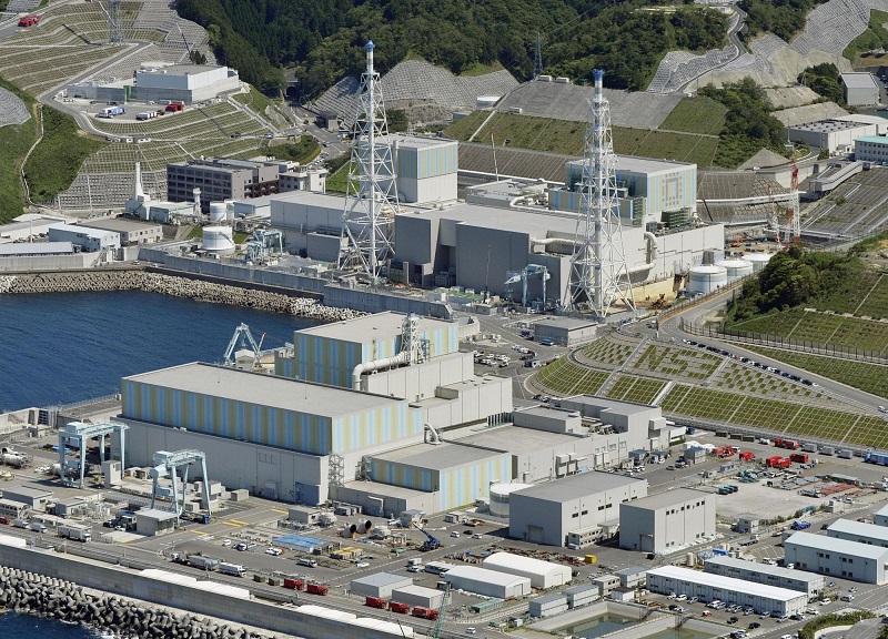
The Fukushima Nuclear Accident was a major nuclear accident at the Fukushima Daiichi nuclear power plant in Ōkuma, Fukushima, Japan which began on March 11, 2011. The real cause of the accident was the 2011 Tōhoku earthquake and tsunami, which resulted in electrical grid failure and damaged nearly all of the power plant's backup energy sources. The subsequent inability to sufficiently cool the reactors after shutdown compromised containment and resulted in the release of radioactive contaminants into the surrounding environment. The accident was rated seven (the maximum severity) on the INES by NISA, following a report by the JNES.
The immediate result of the Fukushima nuclear accident was the loss of interest in funding for any of the Generation IV nuclear technologies.
Section Three: Nuclear Technologies Program
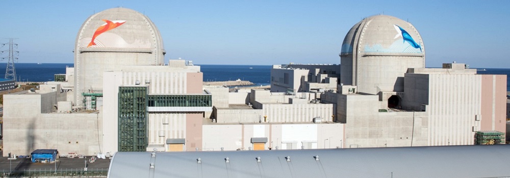
Nuclear Technologies will concentrate its effort and resources, in the inclusion of the following nuclear technologies: the Westinghouse light-water AP-1000 Reactor, the GE Boiling Water Reactor (BWR), the CANDU (Canadian Deuterium Uranium) Reactor and finally we will also have a comprehensive discussion of the HTGR Technology being developed by the Senior Engineer: PBMR (Pebble Bed Modular Reactor)
.3.1: Westinghouse
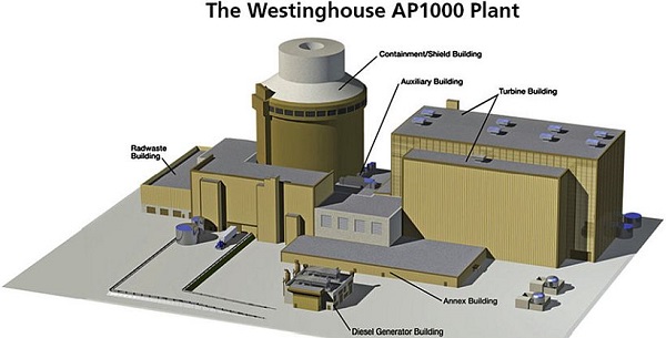
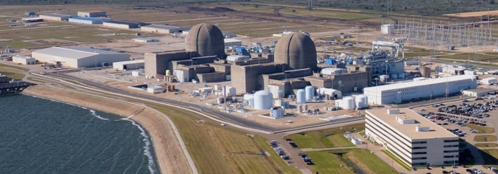
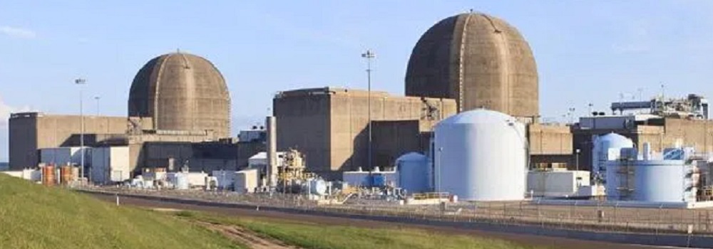
The Westinghouse family of nuclear reactors are classed as Pressurized water reactors (PWRs). This type of reactor technologies comprise a majority of all western nuclear power plants. In a PWR the primary coolant (superheated water) is pumped under high pressure to the reactor core, then the heated water transfers thermal energy to a steam generator. The Nuclear Reactors at Three Mile Island are all PWR, types of reactor. We should mention that they were built by Babcock and Wilcox and not by Westinghouse.
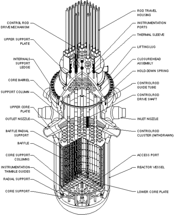
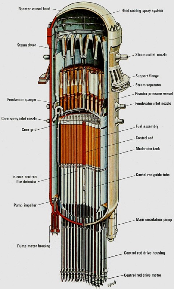
3.1.1: Reactor Pressure Vessel
The central component of the nuclear steam supply system is a heavy-walled reactor vessel that houses the nuclear core and its mechanical control rods, as well as necessary support and alignment structures. It is shown as a cut-away showing the internal details below. The vessel is cylindrical in shape with a hemispherical bottom head and a flanged and gasketed upper head for access. It is fabricated of carbon steel, but all wetted surfaces are clad with stainless steel to limit corrosion. The internal core support and alignment structures are removable to facilitate inspection and maintenance, as is the alignment structure for the top-mounted control rod drive mechanisms. Vessel inlet and outlet nozzles for the primary loops are located at a level well above the top of the fuel core.
8.3 Nuclear Steam Supply System
8.3.1. Fuel Assemblies: Nuclear fuel in the reactor vessel is engaged in a fission chain reaction, which produces heat, heating the water in the primary coolant loop by thermal conduction through the fuel cladding.
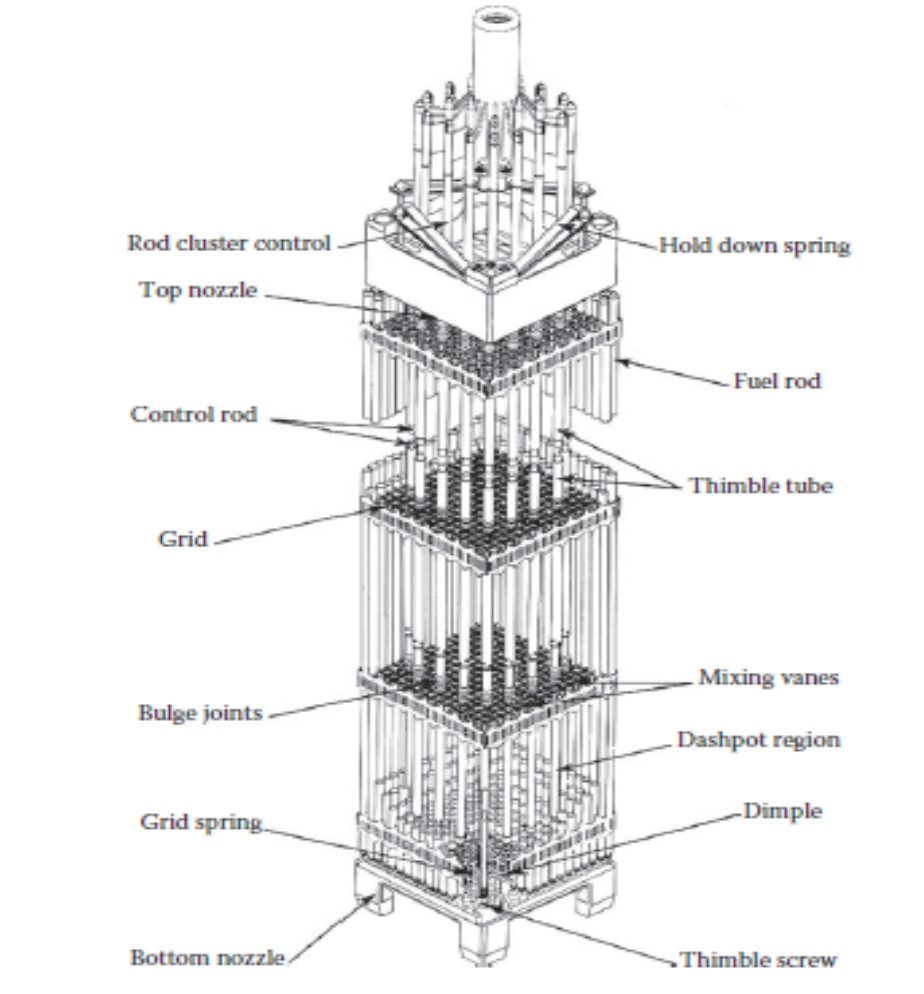
A square array of fuel rods structurally bound together constitutes a fuel assembly. Control rod guide thimbles replace fuel rods at selected spaces in the array and are fastened to the top and bottom nozzles of the assembly. Spring clip grid assemblies are fastened to the guide thimbles along the height of the fuel assembly to provide support for the fuel rods. The fuel rods are contained and supported, and the rod-to-rod centerline spacing is maintained within this skeletal framework. The image below details the assembly showing the structural details. The bottom nozzle of the fuel assembly controls the coolant flow distribution and also serves as the bottom structural element. The top nozzle functions as the fuel assembly upper structural element and forms a plenum space where the heated reactor coolant is mixed and directed toward the flow holes in the upper core plate. The spring clip grids provide support for the fuel rods in two perpendicular directions. Each rod is supported at six points in each cell of the grid. Four support points are fixed: two on one side of the grid strap, and two similarly located on the adjacent side. Two more support points are provided by spring straps located opposite the fixed points. Each spring strap exerts a force on the fuel rod such that lateral fuel rod vibration is restrained, but small thermal expansions are allowed. Because the fuel rods are not physically bound to the support points, they are free to expand axially to accommodate thermal expansion and radiation-induced growth of the highly textured crystal structure of the Zircaloy cladding.
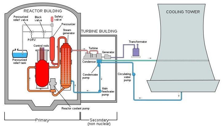
The hot primary coolant is pumped into a heat exchanger called steam generator, where heat is transferred across a set of tubes to the lower pressure secondary coolant, which evaporates to pressurized steam. The transfer of heat is accomplished without mixing the two fluids, which is desirable since the primary coolant might become radioactive.
Two things are characteristic for the pressurized water reactor (PWR) when compared with other reactor types: coolant loop separation from the steam system and pressure inside the primary coolant loop. In a PWR, there are two separate coolant loops (primary and secondary), which are both filled with demineralized/deionized water. The pressure in the primary coolant loop is typically 15–16 megapascals (153 atmospheres, 2,250 psig,150–160 bar), which is notably higher than in other nuclear reactors. As an effect of this, only localized boiling occurs and steam will recondense promptly in the bulk fluid.
2. Primary Loop: The primary loop contains the heat source consisting of a nuclear fuel core positioned within a reactor vessel where the energy resulting from the controlled fission reaction is transformed into sensible heat in the coolant/moderator. The coolant is pumped to the steam generator where the heat is transferred to a secondary loop through several U-type tubes. The reactor coolant then returns back to the reactor vessel to continue the process. An electrically heated pressurizer connected to the loop maintains a pressure above the saturation pressure so that bulk boiling does not occur. See Figure 2.2 for the layout of the RCS. Figure 2.3 is a cut-away of the reactor vessel. Figure 2.10 gives details of the steam generator. Figure 2.9 shows the reactor coolant pump (RCP), and Figure 2.11 is the pressurizer. In the RCS design of plants by C-E, two of the exit loops from the reactor vessel join to feed one steam generator. In a nominal “four-loop” plant, there are two such very large steam generators instead of four.
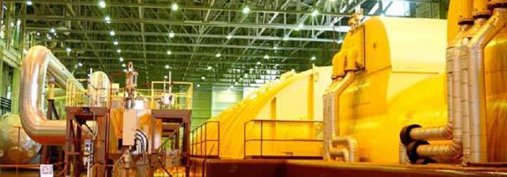
3. Secondary Loop: The secondary loop is the heat utilization circuit where dry steam produced in the steam generator flows to a turbine-generator where it is expanded to convert thermal energy into mechanical energy and hence electrical energy. The expanded steam exhausts to a condenser where the latent heat of vaporization is transferred to the cooling system and is condensed. The condensate is pumped back to the steam generator to continue the cycle.
4. Tertiary Loop: he tertiary loop is the heat rejection loop where the latent heat of vaporization is rejected to the environment through the condenser cooling water. Depending on the specific site, this heat is released to a river, lake, ocean, or cooling tower system. The latter is becoming the more common within the United States in part because of increasingly stringent environmental rules to reduce the thermal impact on natural water bodies.
5. Confinement of Radioactivity:Use of a steam generator to separate the primary loop from the secondary loop largely confines the radioactive materials to a single building during normal power operation and eliminates the extensive turbine maintenance problems that would result from radioactively contaminated steam. Radioactivity sources are the activation products from the small amount of corrosion that is present in the primary loop over the 12–18-month reactor cycle, as well as from the occasional (<1 in 10,000) fuel rod that develops a crack and releases a small portion of its volatile fission products. Uranium dioxide fuel is very resistant to erosion by the coolant, so the rod does not dump its entire fission product inventory into the RCS.
Section Four: Component Design
1. Fuel Assembly: A square array of fuel rods structurally bound together constitutes a fuel assembly. Control rod guide thimbles replace fuel rods at selected spaces in the array and are fastened to the top and bottom nozzles of the assembly. Spring clip grid assemblies are fastened to the guide thimbles along the height of the fuel assembly to provide support for the fuel rods. The fuel rods are contained and supported, and the rod-to-rod centerline spacing is maintained within this skeletal framework.
The bottom nozzle of the fuel assembly controls the coolant flow distribution and also serves as the bottom structural element. The top nozzle functions as the fuel assembly upper structural element and forms a plenum space where the heated reactor coolant is mixed and directed toward the flow holes in the upper core plate. The spring clip grids provide support for the fuel rods in two perpendicular directions.
Each rod is supported at six points in each cell of the grid. Four support points are fixed: two on one side of the grid strap, and two similarly located on the adjacent side. Two more support points are provided by spring straps located opposite the fixed points. Each spring strap exerts a force on the fuel rod such that lateral fuel rod vibration is restrained, but small thermal expansions are allowed. Because the fuel rods are not physically bound to the support points, they are free to expand axially to accommodate thermal expansion and radiation-induced growth of the highly textured crystal structure of the Zircaloy cladding.
2. Grid Assemblies:Two types of grid assemblies are employed. One type features mixing vanes that project from the edges of the straps into the coolant stream to promote mixing of the coolant in the high heat region of the fuel assemblies. The other, a nonmixing type of grid (to minimize flow pressure losses), is located at the bottom and top ends of the assembly where mixing for heat transfer purposes is not needed. The outside straps on all grids contain vanes which aid in guiding the grids and fuel assemblies past projecting surfaces during fuel handling or while loading and unloading the core. All fuel assemblies employ the same basic mechanical design.
3. Other Features of Assemblies: All assemblies can accept control rod clusters (the term “control rod cluster” is also referred to as “RCC” in the literature) but these are not used at every core location. Selected fuel assemblies have neutron sources or burnable absorber rods installed in the control rod guide thimbles. Fuel assemblies not containing RCCs, source assemblies, or burnable absorber rods, are fitted with plugs in the upper nozzle to restrict the flow through the vacant control rod guide thimbles. This plug includes an end-flow mixing device to assure that these fuel assemblies have approximately the same coolant flow as those containing RCCs.
The fuel assembly design provides optimum core performance by minimizing neutron absorption in structural materials and maximizing heat-transfer capabilities. Mixing vane grids increase the heat-transfer capability of the fuel rods. High fuel utilization is achieved by minimizing the parasitic absorption of neutrons in the core. In the assembly design, the only structural materials in the fuel region are the spring clip grids, Zircaloy control rod guide thimbles, and Zircaloy fuel cladding. Zircaloy is used because it absorbs relatively few neutrons and has good mechanical and heat-transfer properties. Because all fuel vendors bid on reloads for each others’ reactor core designs, as well as their own, all design features of each core must be public knowledge. Each reload constitutes one-third of the core, so it must be compatible neutronically and mechanically to fuel already in the core to avoid power generation distortions within the core and equipment mismatches. This applies to all types of reactors, not just PWRs.
4. Control Rods: RCC assemblies are used for reactor startup or shutdown, to follow load changes, and to control small transient changes in reactivity. The control elements of a RCC assembly consist of cylindrical neutron absorber rods (control rods), having approximately the same dimensions as a fuel rod and connected at the top by a spider-like bracket to form rod clusters. The control rods, which are stainless steel tubes encapsulating a hafnium absorber material, extend the full length of the core when fully inserted. Full-length RCCs provide operational reactivity control and can shut the reactor down at all times, even with the most reactive RCC stuck out of the core. Each RCC is coupled to its drive shaft, which is actuated by a separate magnetically actuated drive mechanism mounted on the reactor vessel head. RCCs are arranged into groups and electrically interconnected so that the entire group moves together. Reactivity of the core is changed by raising or lowering a group in the core. Each control rod of a RCC moves vertically in its own tubular guide thimble (an empty tube with a reduced diameter near the base, a plug at the bottom and holes in the smaller diameter section to allow some coolant in or out). Located symmetrically within fuel assemblies, these thimbles replace fuel rods within the fuel assembly lattice. All fuel assemblies are built the same because each could be in a control rod position, or any other position in the core. When an assembly is not in a RCC position, thimbles are plugged or contain BP rods (absorber that is used up during the reactor cycle). The thimbles: (1) act as guides for the control rods; and (2) serve as “dashpots” (shock absorbers) for slowing control rod motion during reactor trip. In their fully withdrawn position, control rods do not leave the upper end of the guide thimbles. This assures that the rods are always properly aligned, and reduces reactor coolant bypass through the thimbles. RCC design contributes to core performance improvement by providing a relatively homogeneous means of control. When control rods are withdrawn from the core, the resulting small water gaps do not cause significant power peaking.
5. Enrichment: Of the 193 fuel assemblies originally contained in a four-loop reactor first core, approximately 65 were of a low enrichment (2.10 weight percent uranium-235), 64 were an intermediate enrichment (2.60 w/o U-235), and 64 were a high enrichment (3.10 w/o U-235). Low and intermediate enrichment assemblies were arranged in a checkerboard pattern in the central portion of the core, whereas high enrichment assemblies were arranged about the periphery of the core. The first fuel cycle usually contained more excess reactivity than subsequent cycles due to the loading of all fresh (unburned) fuel.
If soluble boron were the sole means of control, the concentration would be of the order of 1700 ppm, and the moderator temperature coefficient would be on the order of + 7 pcm/°F (pcm stands for percent mille), A 15°F (9.5°C) increase in moderator temperature creates 0.001 reactivity increase under these high boron conditions]. Because a large positive coefficient is undesirable, a reduction of the amount of control to be provided by chemical shim is accomplished by placing aluminum oxide–boron carbide burnable absorber material in the core. This material is depletable in the same fashion as uranium-235. As the fuel and Burnable Poison (BP) is depleted, the power shifts toward the center of the core, and this shift must be accounted for in design calculations. At the end of life, the power distribution is again quite uniform. Today, these older systems have achieved an optimal balance of BP and reload enrichment to achieve longer core life and much higher burnups than were initially believed possible.
6. Startup: Reactor startup neutron sources must be used to raise the neutron multiplication rate to levels detectable by the flux detectors outside the reactor, but still less than criticality. The fresh fuel configuration and the initially low core reactivity (from random fissions) by themselves would not permit a safely controlled startup.
Neutron sources are of two types: (1) a primary source (which is active for initial reactor startup and startup early in the life of the first core) and (2) a secondary source (used for later startup of the reactor and which is activated during the operation of the reactor).
The primary source is usually a spontaneously fissionable californium isotope. Secondary sources contain a mixture of antimony and beryllium (Sb–Be). The Sb becomes radioactive, emitting high-energy gamma particles that spall neutrons from the Be. The primary and secondary sources are similar to a control rod in mechanical construction. Both types of source rods are clad in stainless steel. The secondary source rods contain Sb–Be pellets which are not initially active. The primary source rods contain sealed capsules of source material at a specified axial position. Cladding encapsulation is completed by seal-welding the end plugs. The specific core location of the sources is determined during final design of the core to assure adequate neutron flux at the source range detectors at all times.
Reactor coolant piping and fittings are made of stainless steel or are carbon steel-clad with stainless steel. Carbon steel is used for the pressurizer relief line which connects the pressurizer safety and relief valves to the flanged nozzle on the pressurizer relief tank, and for the nitrogen supply, vent, and drain lines for the pressurizer relief tank. The pressurizer surge and spray lines, loop drains, and connections to other systems are of austenitic stainless steel. Except for the flanged pressurizer safety valve outlet nozzles, all joints and connections are welded. Thermal sleeves are installed where high thermal stresses could develop because of rapid changes in fluid temperature during transients. Valves, piping, and equipment which operate at elevated temperatures are normally covered with thermal insulation to reduce heat losses. Insulation covering the piping and components of the RCS are designed to facilitate its removal for periodic in-service inspections. Insulation used for the RCS is strictly specified to limit chlorides and other halogens. Reactor vessels are frequently insulated with reflective metal insulation systems.
Sub-part Two: GE Boiling Water Reactor
Introduction to Boiling Water Reactor Technologies
The BWR nuclear plant, like the Pressurized Water Reactor (PWR), has its origins in the technology developed in the 1950s for the United States Navy nuclear submarine program. The first BWR nuclear plant to be built was the 5 MWe Vallecitos Plant (1957) near San Jose, California. The Vallecitos plant confirmed that BWR plants could successfully and safely produce electricity for a grid. The first large-scale BWR, Dresden I, followed in 1960, and since then the BWR design subsequently underwent a series of evolutionary changes with one purpose in mind: simplicity.
The major difference between the PWR and BWR is that the latter is a direct cycle nuclear system with heat generation occurring in the fuel region and water boiling in the envelope of the fuel bundles. This will be explored later. There are approximately 92 operational BWRs in the world today and several Advanced Boiling Water Reactors (ABWRs) currently under construction. This design comprises about 25% of the total number of units in operation globally. Current and former vendors are ASEA-Atom, Kraftwerken Union, Hitachi, Toshiba, and General Electric. Consolidation of the industrial supply base has led to continued partnerships in the nuclear supply chain.
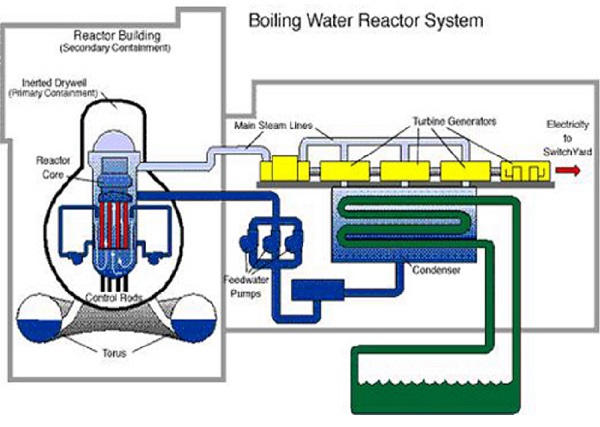
The BWR design has been simplified in two key areas: reactor systems and containment design. Refer to Table 3.1 to see the evolution of simplification. The first BWR, Dresden 1 was, interestingly enough, not a true BWR. The design was based upon dual steam cycle, not the direct steam cycle that characterizes BWRs. Steam was generated in the reactor but then flowed to an elevated steam drum and a secondary steam generator before making its way to the turbine. The first step down the path of simplicity that led ultimately to the ABWR was elimination of the external steam drum by introducing two technical innovations: the internal steam separator and dryer.
General Electric selected the BWR as the most promising nuclear power concept because of its inherent advantages in control and design simplicity, and established an atomic power equipment business in 1955 to offer it commercially. Aside from its heat source, the BWR generation cycle is substantially similar to that found in fossil-fueled power plants.
Sub-part Three: CANDU SMR
Introduction to CANDU
The Senior Engineer of AscenTrust has been involved with the Canadian Deuterium Reactor technologies since 1969. It is therefore natural that we would be involved in the licensing of the CANDU, in the U.S.
The CANDU can only be licensed in the US through the new regulatory environment referred to as 10 CFR Part 53 . As far as licensing is concerned the CANDU has two major technical problems. The first problem is the lack of a pressure vessel and the second is the positive coeficient of reactivity.
The CANDU Owners Group (COG) are proceeding with the development and deployment of advanced technologies and small modular reactors (SMRs) in Canada and worldwide.
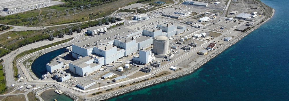
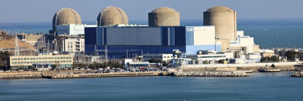
CANDU stands for CANada Deuterium Uranium. A CANDU is a type of nuclear reactor with technology to use non enriched fuel developed by Canada. Currently, seven countries in this world have CANDU type reactors: Canada, India, China, Pakistan, South Korea, Argentina and Romania.
The neutron which is emitted from a nuclear fission reaction is an ~MeV neutron. However, due to the fact that the absorption cross section for Uranium of a thermal(0.025eV) neutron is orders of magnitude higher than MeV neutrons, one needs to thermalize these neutrons. At the same time, we do not want the thermalizeing agent to absorb the neutrons. It is also desirable that a neutron loses a lot of energy in each collision. These factors, are accounted in the number called the Moderating Ratio which is proportional to scattering cross section for neutrons, energy lost in each collision, and inversly proportional to absorption cross section. This number works out to be 58 for light water and 21000 for heavy water. It is this large value of the moderating ratio that allows CANDU reactors to use Natural Uranium without enrighment.
The heavy water coolant flows in pressure tubes horizontally as it provides higher symmetry. However, there is a large mass of the pressure tube inside the reactor and it can potentially absorb too many neutrons to sabotage reactor criticality. The solution to this problem came via Zirconium which happens to have a very low neutron absorption cross section. It is worth mentioning that this result came as a product of materials research in Chalk River for the US nuclear program.
Although, in principle, the coolent can be anything, all operating CANDU reactors have heavy water as coolent as the use of heavy water maximises neutron economy. The advanced CANDU reactors use pressurised light water as coolent.
The CANDU SMR
Section One: Introduction
The CANDU Small Modular Reactor (SMR) is being developed as a proven and mature design to help countries reach their goal of Net Zero. Built on proven CANDU technology to be quickly deployable, this 300 MW(e) reactor features simplified systems, fewer components and a modular design. The design objectives are a low-cost, low-carbon power with a high capacity factor in a compact layout.
Section Two: Target Application
A CANDU SMR is designed to enable a fast deployment using proven technology, maintaining energy independence by using natural uranium fuel from fuel manufacturers and avoiding the need to import enriched uranium fuel. This maximizes identification and utilization of a high performing supply chain, minimizing project delivery risk and creating high technology jobs in countries. The CANDU SMR (CSMR) offers a smaller and more flexible source of carbon-free electricity. The CSMR is a Generation III+ reactor with a design life of 70 years (extendable to 100 years) and a 90% capacity factor. It accommodates to a broad range of potential reactor sites, with its 0.3g seismic design, compact shape and grid-stability features.
Section Three: Main Design Features
1. Design Philosophy: The CSMR is based on a decades-long proven design that is licensed in many countries operating CANDU reactors. It meets modern regulatory requirements, with dedicated post-Fukushima features. The CSMR does not require enriched fuel or a fuel-qualification program because it relies on natural Uranium in the same fuel bundle employed in multiple CANDU6 reactors. To achieve this it uses heavy water for moderation and cooling.
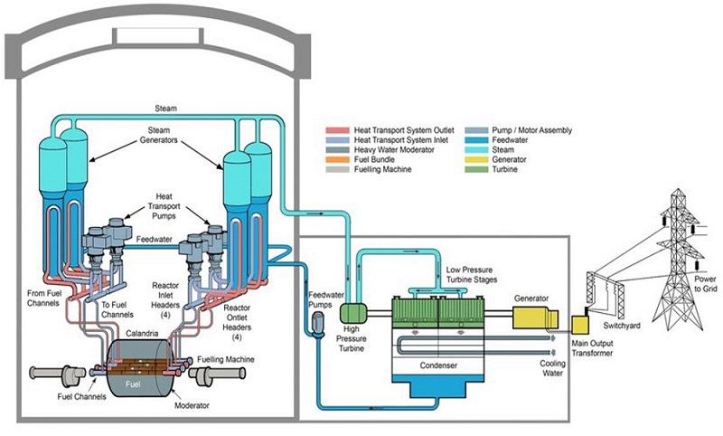
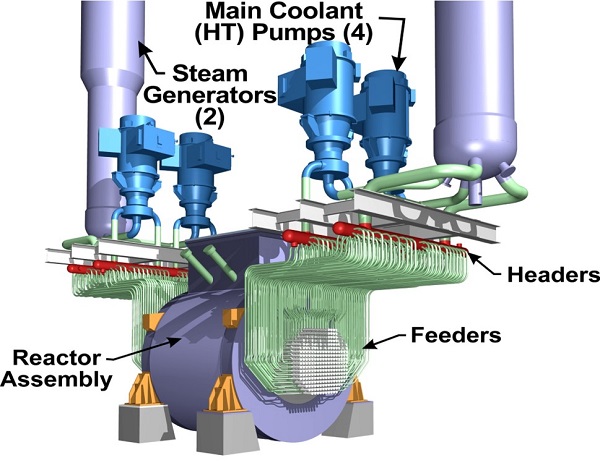
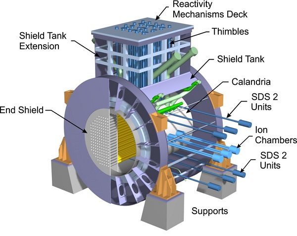
2. Nuclear Steam Supply System: The CSMR is a horizontal pressure tube, pressurized heavy water reactor developed from the long lineage of successful CANDU reactors. The reactor core consists of a horizontal calandria housing a set of pressure tubes. The reactor coolant system consists of these pressure tubes, two steam generators, four primary circulation pumps plus interconnecting piping and headers. The calandria itself is filled with heavy water that surrounds the pressure tubes and provides neutron moderation plus an element of safety, with the calandria operating as a core catcher for severe accidents.
3. Reactor Core:
The CSMR core is 176 channels in a lattice of 14 rows and 14 columns. The channel array is 12’ 2” across. The calandria main shell radius is 285 cm. Reactor is fueled by standard CANDU natural uranium fuel bundle.
4. Reactivity Control: Reactor control uses eight zone control units to provide the primary means of reactivity regulation during normal operation. The core design allows control to be achieved through very small changes in these zone control units. The adjuster rods, absorber rods and ability to use soluble poisons found in traditional CANDU designs are retained, as are two fully independent, diverse safety-shutdown systems: SDS1 and SDS2. Like its predecessors, the CSMR provides safety shutdown reliability.
5. Reactor Pressure Vessel and Internals: The reactor consists of a cylindrical calandria and end shield assembly that is enclosed and supported by the cylindrical shield tank and its end walls. The cylindrical shield tank extension 1assembly closes the top of both vessels. The calandria contains the heavy water moderator and reflector; the shield tank contains light water. The seismically-qualified moderator system is independent from the pressurized heavy water heat transport system (HTS) in the fuel channel assemblies and has the inlet and outlet nozzles connected high in the calandria to enhance performance in the event of a severe accident.
6. Reactor Coolant System: The HTS is a single figure-of-eight loop with two steam generators and four heat transport pumps. The HTS is seismically qualified such that a seismic-induced LOCA is outside of the design basis.
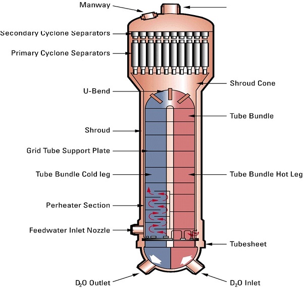
7. Steam Generator: Two steam generators are used, both with inverted U-tubes and integral steam drum and preheaters, and located inside the containment structure.
8. Pressurizer: he pressure and inventory control system include a pressurizer, bleed condenser, feed pumps (one operating; one on standby), a storage tank and control valves.
Section Four: Safety Features
The CSMR safety features establish defence-in-depth against radiological hazards. CSMR leverages the inherent safety characteristics of the basic CANDU reactor design and supplements them with a judicious application of passive and active safety features that emphasizes provenness and results in an improvement in safety. The irradiated fuel bay is a robust, seismically qualified structure with a large volume of water relative to the decay heat load of discharged fuel, providing many days of passive cooling in the event of a loss of active heat removal.
The CSMR provides large volumes of water that are available to provide cooling to the core in the event of accidents, including by passive means. In addition, it has a large containment volume, contributing to minimizing hydrogen concentrations in severe accidents. The CSMR HTS is seismically qualified to the design basis earthquake. The CSMR also makes use of loop subdivision and feeder interlacing to reduce the rate of coolant voiding that is possible in the event of a large HTS pipe break.
The CSMR places all reactivity devices in the separate, low-temperature, low-pressure moderator, eliminating pressure-driven ejection of reactivity devices from the design. The separation of moderator from coolant also provides two separate heat removal means in the event of accidents and ensures that moderator temperature feedback to the core physics is negligible in normal operation. The characteristic CANDU pressure-tube design means that direct containment heating type of severe accident does not occur in this design.
1. Engineered Safety System Approach and Configuration : All plant systems are assigned to one of two groups (group 1 or group 2) according to the CSMR grouping and separation approach. Group 1 includes the power production systems and delivers safety functions for group 2 support. Group 2 includes the safety related systems required for mitigation of accidents and group 2 systems are qualified or protected to provide safety functions in the event of severe external events. There is additional separation within the groups.
The CSMR has two separate shutdown systems. These are two fully-capable fast-acting means of shutdown for use at the third level of defence in depth, fully independent of each other and of the reactor regulating system which acts at the second level of defence in depth.
2. Decay Heat Removal System
Decay heat removal is accomplished in CSMR by application of several provisions in the design, including three group 2 systems, as follows:
The large inventory in the HTS, including the pressurizer inventory, provides heat removal for normal operating transients. The HTS layout enhances natural circulation to the steam generators, which have a large inventory. The steam generators have normal make-up capability and back-up feedwater.
When the steam generators are not available, or are not effective for heat removal, heat can be removed from the HTS using the shutdown cooling system. Under emergency conditions this system can be valved in at full HTS pressure and temperature.
3. Emergency Core Cooling System
The emergency core cooling system supplies emergency coolant to the reactor headers in the event of a loss- of-coolant accident (LOCA). The system operation is divided into two parts, short-term injection and long- term recirculation. Short-term injection consists of two stages: high pressure and low pressure injection. During the high pressure injection stage, water from the accumulator tanks is injected into the HTS by pressurized gas. After this water is depleted, low pressure injection automatically takes over, injecting water from a grade level tank via the emergency core cooling pumps. A connection is provided to this tank for demineralized water makeup, and for initial filling. For small LOCAs provision of steam generator crash cooldown and the maintenance of continued feedwater flow is used instead of the ECC heat exchangers to provide cooling. The crash cooldown is performed via the MSSVs.
4. Containment System
The basic function of the containment system is to form a continuous, pressure-confining envelope about the reactor core and primary cooling system in order to limit the release of radioactive material to the external environment resulting from an accident. This accident could be either a failure of fuel cooling, or an accident which releases radioactive material into the containment without a rise in containment internal pressure.
To achieve this overall function, the containment system includes the following related safety functions:
i. Isolation: to ensure closure of all openings in containment when an accident occurs.
ii. Pressure/activity reduction: to control and assist in reducing the internal pressure and free radioactive material released into containment by an accident.
iii. Hydrogen control: to limit concentrations of hydrogen/deuterium within containment after an accident to prevent detonation.
iv. Monitoring: to monitor conditions within containment and the status of containment equipment, before, during and after an accident.
In addition to its safety role, the containment structure also serves the following functions:
i. To limit the release of radioactive materials from the reactor to the environment during normal operations.
ii. To provide external shielding against radiation sources within containment during normal operations and after an accident.
iii. To protect reactor systems against external events such as tornados, floods, etc.
The containment system includes a reinforced concrete containment structure (the reactor building)with a reinforced concrete dome and an internal steel liner, access airlocks, equipment hatch, building air coolers for pressure reduction, and a containment isolation system.
5. Plant Safety and Operational Performances
The CSMR design aligns with the concept of defence in depth, leveraging inherent safety features through the application of proven engineered systems with an emphasis on providing high reliability through a prudent mix of active and passive features. The overall CSMR design philosophy is to reduce total unit energy cost by reducing specific capital cost, shortening the construction schedule, reducing operating, maintenance and administration costs and providing for plant life extension. In addition, CSMR enhances or improves the traditional CANDU advantages including real safety, low man-rem exposure, high capacity factor and ease of maintenance. Proven systems, system parameters, components, and concepts are used, including proven technologies from other industries.
6. Instrumentation and Control Systems
The overall I&C architecture and design is aligned with the five levels of defense-in-depth, with suitable independence between the different levels. Most automated plant control functions are implemented in a modern distributed control system (DCS) using a network of modular, programmable controllers that communicate with one another using reliable, high-security data transmission methods. The plant is automated to the extent that requires a minimum of operator actions for all phases of operation.
The control systems are backed up by the safety systems, which include the two independent shutdown systems, the emergency core cooling system, emergency heat removal system, and the containment system. Each of these safety systems operates completely independent of the other and independent of the reactor and process control systems.
7. Plant Layout Arrangement
The CSMR layout is arranged to minimize and achieve a short practical construction schedule. This is achieved by simplifying the layout, optimizing interfaces, reducing construction congestion, providing access to all areas, providing flexible equipment installation sequences and reducing material handling requirements. The principal structures of the CSMR include the reactor building, the reactor auxiliary building, the turbine building, the group 1 service building and maintenance building. The auxiliary structures include the Group 1 pump house (main pump house), Group 2 pump house and administration building. In general, Group 1 systems sustain normal plant operation and power production, while Group 2 systems have a safety or safety support functions.
Candu Energy Inc. has requested the CNSC to initiate the formal Vendor Design Review (VDR) process for the CSMR design, which will be conducted based on the regulatory requirements applicable to the new build projects in Canada. The design of CSMR is at the Conceptual Design stage. The current scope is to confirm the safety and OPEX driven design changes affecting NSP in support of licensing review, and to finalize the testing schedule to support Preliminary Safety Analysis Report (PSAR) development and detailed design.
1. Fuel Cycle Approach: The standard CSMR uses a once-through fuel cycle based on natural uranium, producing a very low residual- uranium spent fuel with low heat generation. It is also capable of burning recovered uranium from light-water reactors, making it a valuable addition to any light-water fleet. The use of MOX and Thorium fuels are also possible with suitable customization.
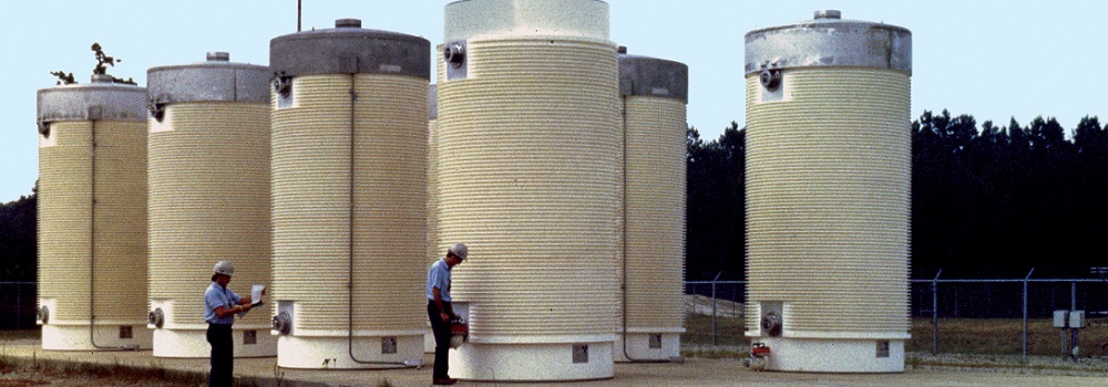
2. Waste Management and Disposal Plan: The CSMR implements systems and equipment for handling radioactive wastes consistent with the state-of- the-art in Canada. The radioactive waste management systems are designed with the objective of limiting routine releases in accord with the ALARA principle. Facilities are provided for interim storage, or controlled release, of all radioactive gaseous, liquid and solid wastes. It is anticipated that most of the of low-level and intermediate-level solid waste produced over the reactor’s 70-plus year lifetime will be stored at the waste management area, with high-level waste being stored on-site in a dry storage facility. Candu Energy Inc. is working on establishing the plan to safely store, handle and dispose of all the spent fuel including the on-site storage, long term storage and potential design for new long- term storage containers that meet the requirements for the deep geological repository design of the Nuclear Waste Management Organization (NWMO).
Sub-part Three: The Nuclear Technology Pebble Bed Modular Reactor
Section One: History of High-Temperature Gas Cooled Reactors (HTGR)
The HTGR concept evolved from early air-cooled and Carbon-dioxide-cooled reactors. The use of helium in lieu of air or Carbon dioxide as the coolant, in combination with a graphite moderator, offered enhanced neutronic and thermal efficiencies. The combination helium cooling and graphite moderator makes possible production of high temperature nuclear heat, and hence the name HTGR.
To date, seven HTGR plants have been built and operated. The first was the 20-MW(t) Dragon test reactor in the UK. Dragon was followed by construction of two relatively low power plants, the 115-MW(t) Peach Bottom I (PB-1) in the United States and the 49-MW(t) AVR in Germany. PB-1 and AVR demonstrated electricity generation from HTGR nuclear heat using the Rankine (steam) cycle. These two plants were followed by the construction of two mid-size steam cycle plants, the 842-MW(t) Fort St. Vrain (FSV) plant in the United States and the 750-MW(t) THTR plant in Germany. In addition to demonstrating the use of helium coolant (with outlet temperatures as high as 950°C) and graphite moderator, these early plants also demonstrated coated particle fuel, a fuel form that employs ceramic coatings for containment of fission products at high temperature, which is a key feature of HTGRs.
Section Two: High-Temperature Gas Cooled Reactors (HTGR) Similarities
The Fuel Element: All HTGR designs utilize a refractory coated particle fuel. These particles are identified as BISO- or TRISO-coated particle fuel, which consists of a spherical kernel of fissile and/or fertile fuel material (as appropriate for the application), encapsulated in multiple lay- ers of refractory coatings. The multiple coating layers form a miniature, highly corrosion-resistant pressure vessel and an essentially impermeable barrier to the release of gaseous and metallic fission products. The BISO type is no longer in use within currently operating HTGRs, mainly due to its inferior performance and fission product retention compared with the TRISO type. The BISO is therefore just a historical note, and for the remainder of this chapter all fuel particles shall refer to the TRISO type, as shown in the Figure below. The overall diameter of standard TRISO-coated particles can vary between 650 microns to 850 microns, depending upon the burnup goal and type of fuel utilized (fissile versus fertile).
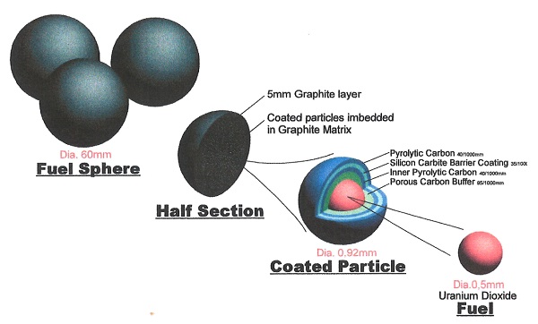
The fuel kernel may be of oxide, carbide, or oxycarbide in composition. For high burnup applications, an oxycarbide kernel is preferred to enhance performance. The carbide component of the kernel undergoes oxidation to getter excess oxygen released during fission. If the carbide component were not present, excess oxygen would react with carbon in the buffer to form carbon monoxide. High levels of carbon monoxide can lead to failure of the coating system by overpressurization and kernel migration.
The buffer layer is deposited over the kernel and consists of low-density, porous pyrocarbon.
The buffer attenuates fission fragments that recoil from the kernel and provides sufficient void space to accommodate gases, including gaseous fission products and carbon monoxide. The buffer also acts as a sacrificial layer to accommodate potential kernel migration and swelling and isolates the kernel from load-bearing layers of the coating system.
The high-density inner pyrolytic carbon (IPyC) layer protects the kernel and buffer from chemical attack by chlorine compounds, which are generated as byproducts during deposition of the silicon carbide (SiC) layer. The IPyC layer also provides a surface for deposition of the SiC layer and delays transport of radionuclides to the SiC layer. The IPyC layer shrinks with the accumulation of fast neutron fluence, which helps to maintain the SiC layer in compression, provided the bond between the IPyC and SiC layers remains strong and continuous during irradiation.
The SiC layer is deposited under conditions that produce a high-density, high-strength coating with a fine-grain microstructure. This layer provides the primary structural support to accommodate stresses generated by internal gas pressure and irradiation-induced dimensional changes of the pyrocarbon layers. The SiC layer provides an impermeable barrier to gaseous, volatile, and most metallic fission products during normal operation and hypothetical accidents. Dimensional changes of the SiC are very small during irradiation, and it is considered to be dimensionally stable.
The high-density outer pyrolytic carbon (OPyC) layer protects the SiC layer from mechanical damage that may occur during fabrication of fuel compacts and fuel elements, and provides a bonding surface for the compact matrix. The OPyC layer also shrinks during irradiation, which helps to maintain the SiC layer in compression. The OPyC layer prevents the release of gaseous fission products if both the IPyC and SiC layers are defective or fail in service.
The TRISO coatings provide a high-temperature, high-integrity structure for retention of fission products to very high burnups. The coatings do not start to thermally degrade until temperatures approaching 2000°C are reached. For example, typically for a reactor outlet coolant temperature of 850°C, normal operating fuel kernel temperatures do not exceed about 1250°C and worst-case accident temperatures are maintained below 1600°C. Extensive tests in the United States, Europe, and Japan have demonstrated the performance potential of this fuel, but tests still need to be done to demonstrate it satisfies Generation IV performance requirements or normal operating and accident conditions.
Sub-part Four: The Nuclear Technology Pebble Bed Modular Reactor
Section One: The Nuclear Island
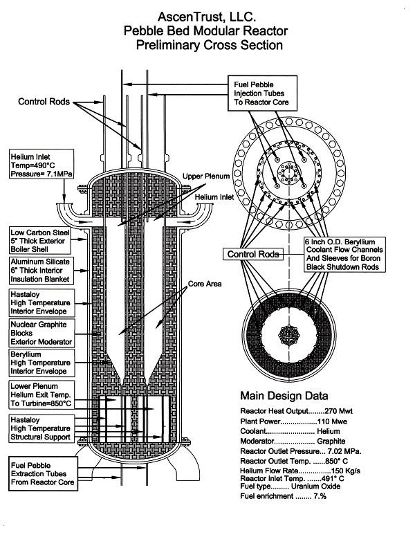
1. On-line refueling capability: A unique feature of pebble bed reactor is the online refueling capability in which the pebbles are re-circulated with checks on integrity and consumption of uranium. This system allows new fuel to be inserted during operation and used or damaged fuel to be discharged and stored on site for the life of the plant. Overall burn-up is increased through this recycling. The online refueling capability allows for the extraction of all the nuclear fuel in the event of a LOCA. Extraction of all the fuel elements in the core in the case of a nuclear event will ensure that the fuel elements will remain intact through the nuclear event without the possibility the fuel pebbles will melt.